Computer Based Systems Honors Project Report
Turtlebot, Remotely Controlled Drawing Robot
Spring 2024
By Skylar Araujo
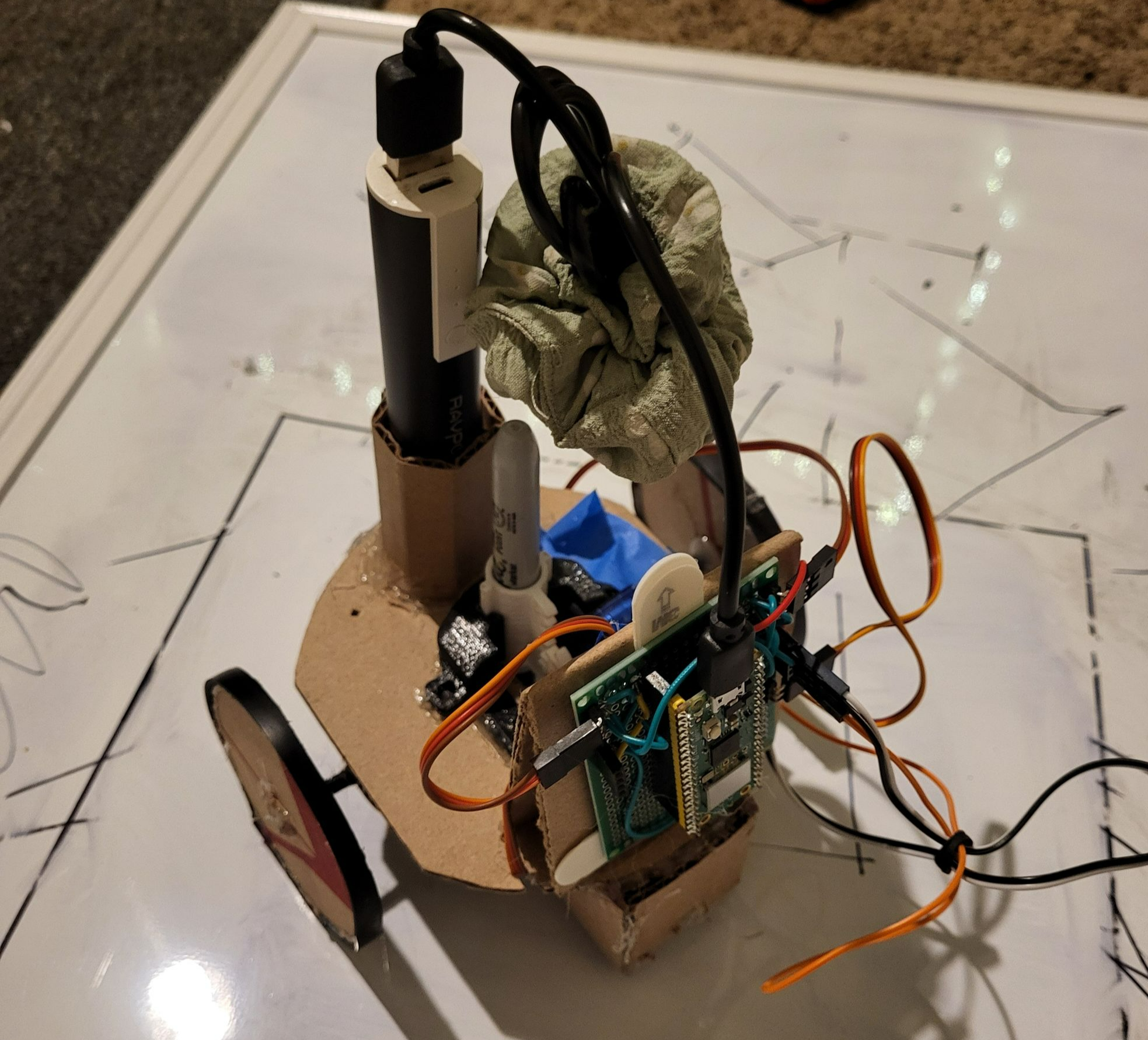
Table of Contents
Introduction
For my ECEN 3213 Computer Based Systems honors project I have chosen to expand upon a project I worked on previously for an IEEE event. I had worked on the first iteration of this project with two peers as the main programmer. In order to meet the requirements for the honors contract I remade the robot from scratch and improved upon it in areas where it had been lacking in its first iteration.
The purpose of the robot is to remotely receive user input and draw pictures based on this input. The first iteration of this robot presented the user with a selection of hard coded preset drawings, and did not allow for the user to create new drawings without reprogramming the robot. My main goal for this project was to redo the user interface so as to allow dynamic control over the robots drawings. Rather than select from a selection of preset drawings, I wanted the user to be able to draw an image on their phone, and watch as the robot mimicked their drawing in real life.
Materials
- Raspberry Pi Pico W
- The Pico W is what controls the robot. It hosts the user interface, receives and processes user data, reads encoder signals, and powers the servos connected to it.
- For the second iteration of the robot it is programmed in C, using the Pico C/C++ SDK.
- Uses the RP2040, a 32-bit dual ARM Cortex-M0+ microcontroller.
- Servo motor
- A position based motor that can be set to a specific position based on a PWM input. Used to lift and lower the pen.
- Continuous Servo Motor
- Continuous servo motors are servos that do not have limits in their rotations. While still taking a PWM input, rather than controlling its position, the PWM controls its speed and direction. Two are used to drive the robot.
- LM393 Encoder
- An encoder that utilizes an infrared light that when obstructed sends out a signal. This encoder is used for odometry, to track the distance travel and rotation of the robot.
- Swivel Ball Castor Wheels
- Used to stabilize the robot with as little friction as possible.
- Protoboard
- The protoboard consists of several headers to connect the microcontroller to all of the motors and sensors.
- Battery, DC 5V/1A
- Used to power the robot.
- Frame
- The frame holds the robot together, it is mostly cardboard, but has a few 3D printed components.
Method
Software
The robot is programmed in C using the Pico C/C++ SDK [1]. This SDK provides functions and libraries useful for utilizing the GPIO pins and the wifi/bluetooth capabilities of the pico. My project setup is based on the Pico W Webserver Template by LearnEmbeddedSystems [2]. I used this template to gain a better understanding on how to host a webpage through the pico, and expanded upon it to suit the needs of my project. To control the servos I used a library created by Thomas Kleist that provides functions for controlling servos in C on a raspberry pico [3]. In order to compile my code I utilize CMake to generate a uf2 file that can simply be dragged and dropped into the pico.
There are two main components of the software, the front-end user interface and the back-end controls. The user interface is the means for which the user interacts with the robot, inputting data and running the robot. The back-end processes the data, converting it into a usable form, calculating distances, angles, and running motors to complete the user's drawing.
User Interface
The UI that controls the robot is a web-page hosted through the raspberry pi pico w. As long as the user is connected to the same network as the pico, they can connect to the robot and access the UI by entering the pico’s IP address into a web browser. Upon boot the pico will first run the file pico_web.c which connects to the network and hosts the web page. This program comes from the web server template, and is mostly unchanged, aside from the network the pico connects to.
Figure 1: pico_web.c
#include "lwip/apps/httpd.h"
#include "pico/stdlib.h"
#include "pico/cyw43_arch.h"
#include "lwipopts.h"
#include "../ssi.h"
#include "../cgi.h"


const char WIFI_SSID[] = "SkylarsHotspot";
const char WIFI_PASSWORD[] = "wifiPassword1";
int main() {
    // initializing important things such as usb communication
    stdio_init_all();


    // initializing the wifi chip
    cyw43_arch_init();


    cyw43_arch_enable_sta_mode();


    // Connect to the WiFI network - loop until connected
    while(cyw43_arch_wifi_connect_timeout_ms(WIFI_SSID, WIFI_PASSWORD, CYW43_AUTH_WPA2_AES_PSK, 30000) != 0){
        printf("Attempting to connect...\n");
    }
    // Print a success message once connected
    printf("Connected! \n");

    // Initialise web server
    httpd_init();
    printf("Http server initialised\n");


    // Configure SSI and CGI handler
    ssi_init();
    printf("SSI Handler initialised\n");
    cgi_init();
    printf("CGI Handler initialised\n");

    // Infinite loop
    while(1);
}
The webpage hosted is a simple html and javascript file. The webpage consists of a square canvas, a toggle between pen up and pen down, a button to run the robot, and other various tools for debugging. When the user clicks in the square canvas, a line will be drawn from the center of the canvas to the point at which the user clicked, further clicks will create new lines connected from the previous point to the new point. By toggling between pen up and pen down, the lines change colors, signifying the state of the pen for that path. Each click stores an xy coordinate and the pen state into arrays. Once the user has finished plotting their lines, clicking the run button with create a string consisting of the number of lines, the x value, y value, and pen state for each line in the following format:
n, x1, y1, p1, x2, y2, p2, . . . , xn, yn,pn

This will then be attached to the end of this link, /data.cgi?data=, and called upon.
The html and javascript are in the same file, but for the sake of readability are separated into two different figures.
Figure 2: index.shtml, html portion
<!DOCTYPE html>
<html>
    <head>
        <title>Turtle Bot Control</title>
    </head>
    <body>
        <h1>Turtle Bot Control</h1>
        <p>This is where Turtlebots controls will be</p>
        <p id = "mouse_x">Mouse X pos: </p>
        <p id = "mouse_y">Mouse Y pos: </p>
        <p id = 'index'>Index:  Mod: </p>
        <canvas id="TurtlePlot" width="400px" height="400px" onclick="show_coords(event)" style="border: 1px solid black;"></canvas>
        <br>
        <form onchange="selection_change()">
            <input type="radio" id="pendwon" name="pen_toggle" value="pendown">
            <label for="pen_toggle">Pen Down</label>
            <input type="radio" id="penup" name="pen_toggle" value="penup" checked="checked">
            <label for="pen_toggle">Pen Up</label>
        </form>


        <a id="run_button" href="/led.cgi?led=0" onclick="run_code()"><button>Run</button></a>

</script> … (See Figure 3)
</script>


    </body>
</html>
Figure 3: index.shtml, javascript portion
<script>
// creating the canvas
const canvas = document.getElementById("TurtlePlot");
const ctx = canvas.getContext("2d");


// defining variables
let i = 0;
let imod = i %2
let x_start; let y_start; let x_end; let y_end; let dist;
let x_vals = []; let y_vals = []; let pen_pos = []; let url;
let pen_stroke = "penup"; let info = "3,5";
// updating index counter display
document.getElementById("index").innerHTML = "Index: " + i + " Mod: " + imod;


// runs the url construction function and sends the data via a link
function run_code() {
  make_url()
  document.getElementById("run_button").href="/data.cgi?data=" + url;
}

// Changes pen selection
function selection_change() {
  pen_stroke = document.querySelector('input[name="pen_toggle"]:checked').value;
  pen_val_text = document.getElementById("pen_val").innerHTML = "Pen Value:   " + pen_stroke;
}


// Stores point coords, updates coord info on webpage, and calls plot_line
function show_coords(event) {
  let x = event.clientX;
  let y = event.clientY;


  x_vals.push(x -208);
  y_vals.push(-1*(y -419));

  let text_x = "Mouse X pos: " + x;
  let text_y = "Mouse Y pos: " + (-1*y);
  let text_x_arr = "X Vals: " + x_vals;
  let text_y_arr = "Y Vals: " + (-1*y_vals);
  let text_p_arr = "P Vals: " + pen_pos;
  let cx = "    Canvas X pos: " + (x -208);
  let cy = "    Canvas Y pos: " + (-1* (y -419));
  i+=1;
  imod = i % 2;
  document.getElementById("mouse_x").innerHTML = text_x + cx;
  document.getElementById("mouse_y").innerHTML = text_y + cy;
  document.getElementById("index").innerHTML = "Index: " + i + " Mod: " + imod;

  if (i ==1) {
    x_start = 208;
    y_start = 419;
    x_end = x;
    y_end = y;
    plot_line(x_start, y_start, x_end, y_end, pen_stroke);
   }
   else {
     x_start = x_end;
     y_start = y_end;
     x_end = x;
     y_end = y;
     plot_line(x_start, y_start, x_end, y_end, pen_stroke);
    }
}


// Plots line visually on canvas
function plot_line(x1, y1, x2, y2, style) {
  ctx.beginPath();


  ctx.moveTo(x1-8, y1-219);
  ctx.lineTo(x2-8, y2-219);
  dist = Math.sqrt(Math.pow(x2 - x1, 2) + Math.pow(y2 - y1, 2));


  if (style == "pendown") {
    ctx.strokeStyle = "black";
    pen_pos.push(1);
  }
  else {
    ctx.strokeStyle = "cyan";
    pen_pos.push(0);
  }
  ctx.stroke();
}

// Combines xy info, pen states, and number of lines into one string
function make_url(){
  for(let q = 0; q < i; q++){
    if (q==0){
      url = i;
      url += "," + x_vals[0] + "," + y_vals[0] + "," + pen_pos[0];
    }
    else{
      url += "," + x_vals[q] + "," + y_vals[q] + "," + pen_pos[q];
    }
  }
  let text_url = "URL: " + url;
  document.getElementById("url_p").innerHTML = text_url;
}
</script>
Common Gateway Interface
In order for the webpage to communicate with the raspberry pi, I use a Common Gateway Interface. This program listens for an http request from the webpage, and upon receiving one runs functions based on the request. In my case, the CGI is listening for /data.cgi?data=”user data”. Upon receiving this request, the program will take the data string, convert it into an integer array, and deconstruct the array into several subarrays. This data is then inputted into functions that run the robot.
Figure 4: cgi.h
#include <stdlib.h>
#include "lwip/apps/httpd.h"
#include "pico/cyw43_arch.h"
#include "servo.h"
#include "math.h"
#include "controls.c"


(These first two functions are irrelevant to the project, the first was apart of the template I used and the second I created while testing)
// CGI handler which is run when a request for /led.cgi is detected
const char * cgi_led_handler(int iIndex, int iNumParams, char *pcParam[], char *pcValue[]) {...}
const char * cgi_forward_handler(int iIndex, int iNumParams, char *pcParam[], char *pcValue[]) {...}


// CGI handler which is run when a request for /data.cgi is detected
const char *cgi_data_handler(int iIndex, int iNumParams, char *pcParam[], char *pcValue[])
{
    cyw43_arch_gpio_put(CYW43_WL_GPIO_LED_PIN, 0);


    // Checking for request for data, ( /data.cgi?data=x )
    if(strcmp(pcParam[0], "data") == 0) {


        /*
        Data is given as a string of chars like this: "1, 2, 3, 4, 5, ..."
        To use this data we must convert to an actual int array, and then
        separated the data into
        arrays for x values, y values, and pen values.


        The data includes the number of lines drawn, the (x,y) points, and
        the pen
        position at each given point, represented by 0 or 1.


        The first point is always assumed to be at (0,0), thus doesn't need
        to be included
        in the given data.


        The data is formated like so:
            "Number of lines, x1, y1, p1, x2, y2, p2, ..., xn, yn, pn"
        */


        // var to hold number of lines, and iteration counter
        int num_lines;
        int i = 0;


        // The following is taking the first element of the data string,
        converting it to an int. Probably a better way to do this but this
        was easier
        char *token;
        token = strtok(pcValue[0], ",");
        while (token !=NULL) {
            num_lines = atoi(token);
            token = strtok(NULL, ",");
            break;
        }
        // Initializing an array with the size three times the number of
        lines
        int data_int[num_lines*3];


        // The following is converting the rest of the data from a
       string to an int array
        while (token !=NULL) {
            data_int[i] = atoi(token);
            token = strtok(NULL, ",");
            i++;
        }


        // defining arrays
        int x_vals[num_lines];
        int y_vals[num_lines];
        int pen_vals[num_lines];


        // separating the data int array into the x, y, and pen arrays.
        for (int k = 0; k<num_lines;k++) {
            x_vals[k] = data_int[0+(k*3)];
            y_vals[k] = data_int[1+(k*3)];
            pen_vals[k] = data_int[2+(k*3)];
        }

        // running the init function and iterating through the draw line
        function
        init();
        for (int z = 0; z < num_lines; z++) {
            draw_line(z, x_vals[z-1], y_vals[z-1], x_vals[z], y_vals[z], pen_vals[z]);
        }
        pen(0);
    }


    return "/index.shtml";
}


// tCGI Struct
// Fill this with all of the CGI requests and their respective handlers
static const tCGI cgi_handlers[] = {
    {
        "/led.cgi", cgi_led_handler
    },
    {
        "/forward.cgi", cgi_forward_handler
    },
    {
        // Html request for "/data.cgi" triggers cgi_data_handler
        "/data.cgi", cgi_data_handler
    },
};


void cgi_init(void)
{
    http_set_cgi_handlers(cgi_handlers, 1);
    http_set_cgi_handlers(cgi_handlers, 2);
    http_set_cgi_handlers(cgi_handlers, 3);
}
Control Functions
Once the robot receives the user data, cgi.h loops the data through draw_line, which is a function from controls.c. The function draw_line calls other functions from within controls.c in order to complete the user inputted paths.
Figure 5: controls.c
#include "pico/stdlib.h"
#include "pico/cyw43_arch.h"
#include "servo.h"


int Pen_Holder = 16;


float unit_to_in = 0.02875; // 11.5in/400
float in_to_tick = 3;
float deg_to_tick = 0.1778;


int Encoder1_D0 = 27;
int SERVO_PIN1 = 28;
int SERVO_PIN2 = 3;


// initializing encoder and servos
void init(){
    gpio_init(Encoder1_D0);
    gpio_set_dir(Encoder1_D0, GPIO_IN);
    setServo(SERVO_PIN1, 0);
    setServo(SERVO_PIN2, 0);
    cyw43_arch_gpio_put(CYW43_WL_GPIO_LED_PIN, 0);
}


// Calcs length between two points
float length(int xi, int yi, int xf, int yf) {
    int x_diff = xf - xi;
    int y_diff = yf - yi;
    float len = sqrt( pow(x_diff, 2) + pow(y_diff, 2) );
    return len;
}


// lifts and lowers pen
int pen(int state) {
    if (state ==0)
        setServo(Pen_Holder, 600); // lift pen
    else
        setServo(Pen_Holder, 1200); // lower pen
}


// converts rotation angle to encoder ticks, runs motors for the amount of ticks
void run_rot(float angle) {
    int dist_ticks = (int)(abs(angle) * deg_to_tick);
    int ticks = 0;
    bool can_count = false;
    bool can_count2 = true;


    while (ticks<dist_ticks){
        // the sign of the angle determines whether the robot rotates left or right
        if (angle > 0){ // rotate right
            setMillis(SERVO_PIN1, 2400);
            setMillis(SERVO_PIN2, 2400);
        }
        else { // rotate left
            setMillis(SERVO_PIN1, 400);
            setMillis(SERVO_PIN2, 400);
        }
        // counting encoder ticks
        if (gpio_get(Encoder1_D0)){
            cyw43_arch_gpio_put(CYW43_WL_GPIO_LED_PIN, 1);
            if(can_count2){
                ticks++;
                can_count2 =false;
            }
            can_count =true;
        }
        else{
            cyw43_arch_gpio_put(CYW43_WL_GPIO_LED_PIN, 0);
            if(can_count){
                ticks++;
                can_count = false;
            }
            can_count2 =true;
        }
    }
    //stopping motors and resetting counter once finished
    setMillis(SERVO_PIN1, 0);
    setMillis(SERVO_PIN2, 0);
    sleep_ms(250);
    ticks = 0;
}


// calculating rotation. Issues here.
float rotate(int xi,int yi,int xf, int yf, float off_ang){
    int neg_dir;
    float next_offset;

    // offset points
    int o_xi = 0;
    int o_yi = 0;
    int o_xf = xf - xi;
    int o_yf = yf - yi;

    if ( (o_xf <= 0 && o_yf >= 0) || (o_xf <= 0 && o_yf <= 0))
        neg_dir = 1;
    else
        neg_dir = 0;


    // y point for third line, to create right triangle, x is 0
    int ym = o_yf;


    // length from (xi,yi) to (xf,yf)
    float H = length(0, 0, o_xf, o_yf);
    float angle = (180/3.14)*acos(o_yf/H);
    if (neg_dir==1)
        angle *= -1;
    angle = angle - off_ang;
    next_offset = angle + off_ang;
    run_rot(angle);
    return next_offset;
}


// moves robot forward, points inputted into length func and converted to ticks
void move(int xi, int yi, int xf, int yf) {
    float dist = length(xi, yi,xf,yf);
    int dist_ticks = (int)(dist * unit_to_in * in_to_tick);
    int ticks = 0;
    bool can_count = false;
    bool can_count2 = true;


    // runs motors for number of ticks calculated
    while (ticks<dist_ticks){
        setMillis(SERVO_PIN1, 400);
        setMillis(SERVO_PIN2, 2400);
        if (gpio_get(Encoder1_D0)){
            cyw43_arch_gpio_put(CYW43_WL_GPIO_LED_PIN, 1);
            if(can_count2){
                ticks++;
                can_count2 =false;
            }
            can_count =true;
        }
        else{
            cyw43_arch_gpio_put(CYW43_WL_GPIO_LED_PIN, 0);
            if(can_count){
                ticks++;
                can_count = false;
            }
            can_count2 =true;
        }
    }


    // setting motors to zero and resetting counter once done
    setMillis(SERVO_PIN1, 0);
    setMillis(SERVO_PIN2, 0);
    sleep_ms(250);
    ticks = 0;
}


// This func gathers all the needed data and calls funcs required to draw out a line
// Lifts pen, rotates, changes pen state, and then moves forwards
int draw_line(int iteration,int xi,int yi,int xf,int yf,int p) {
    pen(0);
    sleep_ms(250);
    float rot;
    if(iteration==0){
        rot = rotate(0, 0, xf, yf, 0);
        sleep_ms(250);
        pen(p);
        sleep_ms(250);
        move(0,0,xf,yf);}
    else{
        rot = rotate(xi, yi, xf, yf, rot);
        sleep_ms(250);
        pen(p);
        sleep_ms(250);
        move(xi,yi,xf,yf);}
}
There are several functions in this file each contributing to drawing the user data.
- init()
This function simply initializes the encoder and motors.
- length(int xi, int yi, int xf, int yf)
This function takes two points and calculates the distance between the two with this formula:
- pen(int state)
This function lifts or lowers the pen based on whether it receives a 0 or 1 as an input.
- run_rot(float angle)
This function takes the calculated rotation angle and converts it to encoder ticks. The direction the robot rotates is dependent on the sign of the angle. The robot will rotate until the encoders count up to the desired value.
- rotate(int xi,int yi,int xf, int yf, float off_ang)
This function takes two points and an angle. The initial point is set to zero, and the final point is subtracted by the initial point. This is to make the calculations easier by orientating it at the origin. With these two points I can find the hypotenuse and the adjacent side, calculating the angle with inverse cosine.
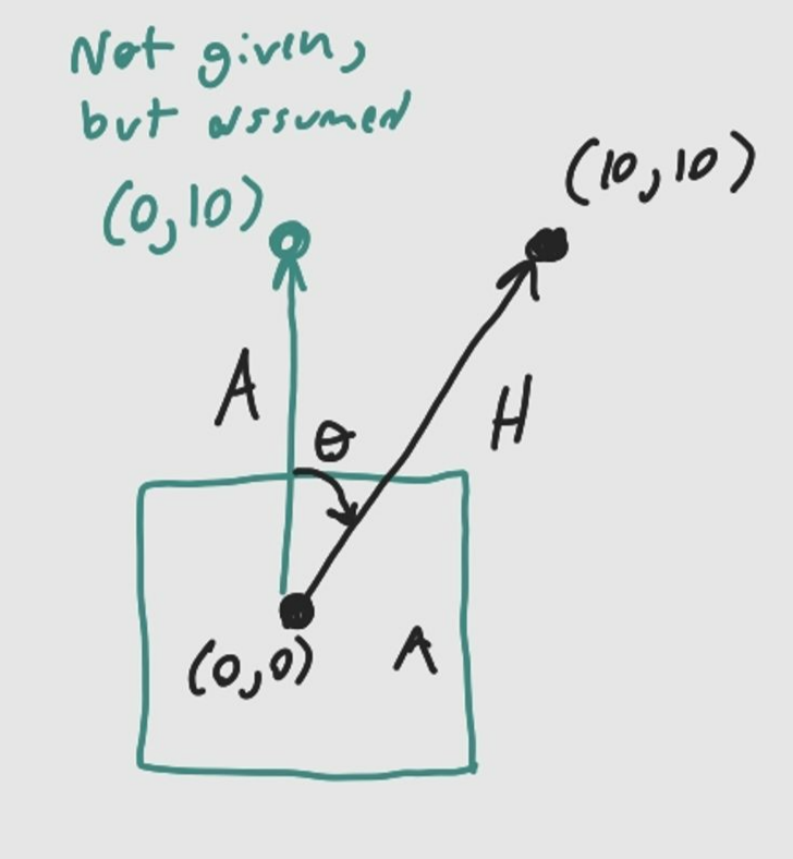
Figure 6: Drawing of the robot facing the top of the canvas with an initial point at (0,0), a final point at (10,10), and an assumed point at (0,10).
When calculating the angle, it is done so with the assumption that the robot is facing the top of the canvas, however this is not always the case. To account for this, the sum of the previous
rotations are inputted as an offset angle, and the calculated angle is subtracted by the offset angle.
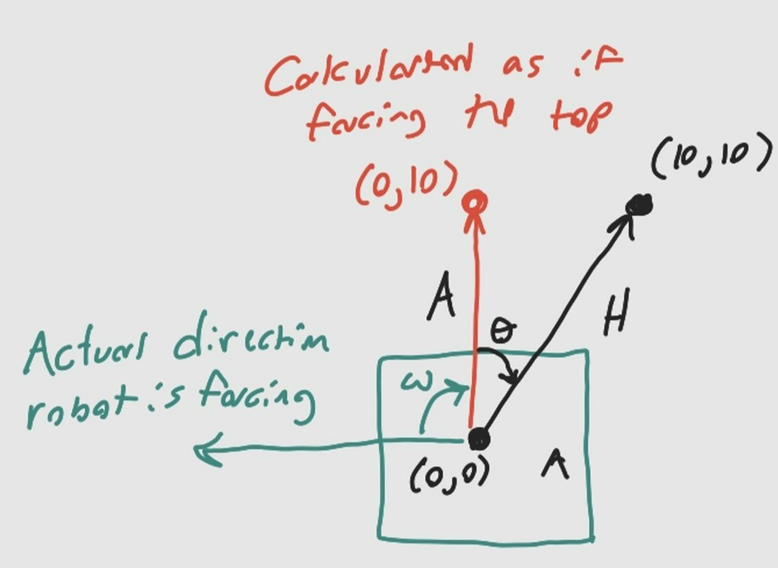
Figure 7: Drawing of the robot facing the left side of the canvas, but the rotation is calculated as if it is facing the top offset angle
Assuming the the previous rotation was -90°, the offset will be -90°
After calculating θ, it is subtracted by the offset angle to get the actual angle the robot will need to rotate.
However, this function has flaws that will be discussed later in this report.
- move(int xi, int yi, int xf, int yf)
The move function takes an initial point and a final point as inputs, passes these values through the length function, converts the calculated distance to ticks, and runs the motors forward until the desired distance is reached.
- draw_line(int iteration,int xi,int yi,int xf,int yf,int p)
As mentioned before, the function draw_line simply collects all the required data and passes it through each of the functions in order to create a line.
Hardware
The Microcontroller
The microcontroller is the most important part of this entire build. This single component drives all the motors, hosts the UI, gathers encoder input, and gathers user input. In labs we have been learning with the raspberry pi, however for this project I have chosen to use the raspberry pi pico w instead. The reason I chose to use the pico w over a normal raspberry pi is that an operating system is not necessary for this project, nor are the ports that come with a regular raspberry pi. A regular raspberry pi would also greatly increase the size of the robot. The pico w only has GPIO pins, which is more than enough to connect the motors and sensors needed for this project.
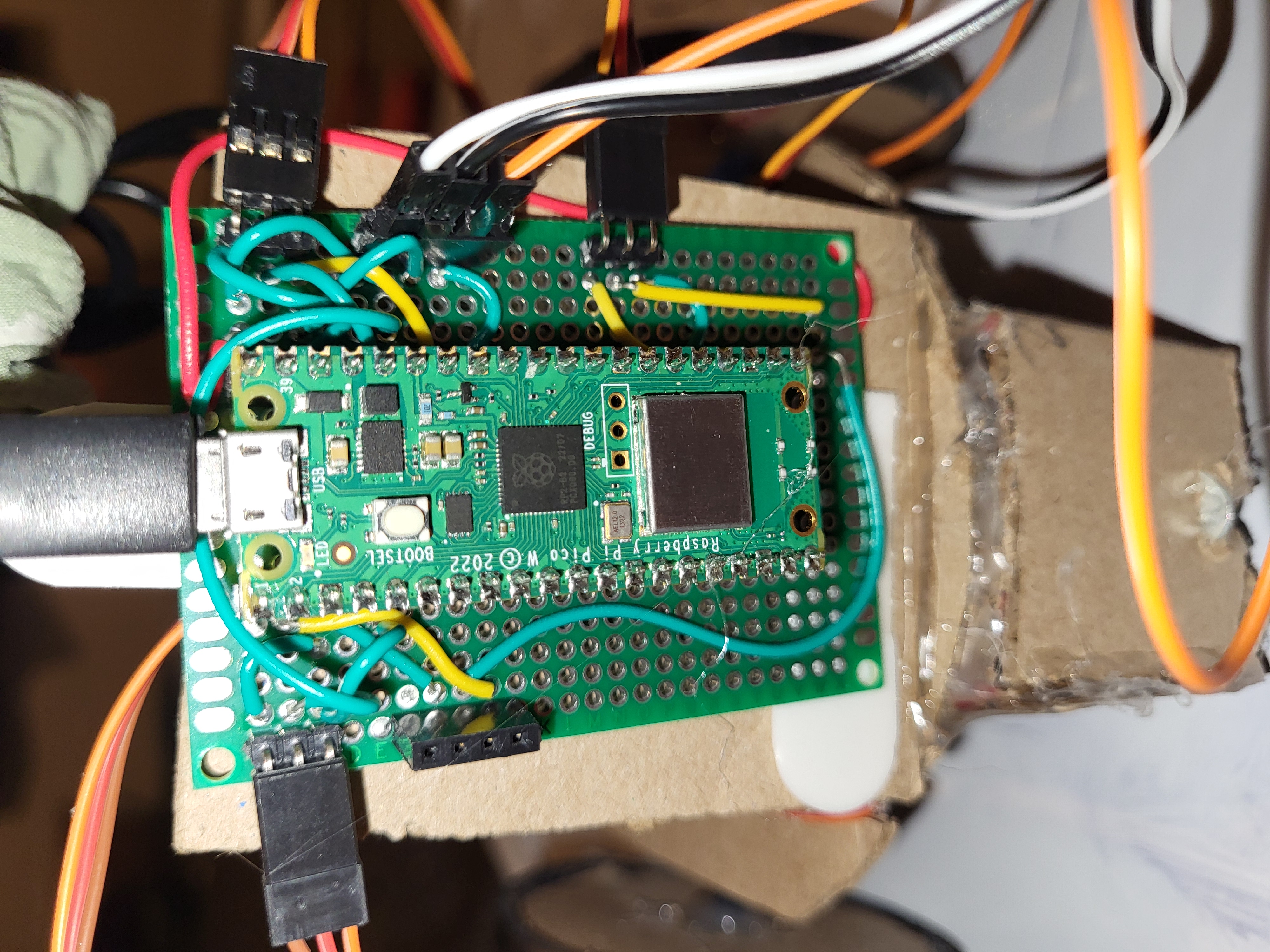
Figure 8: Pico W connected to the turtlebots protoboard, connecting the motors and encoder.
The Motors and the Encoder
To drive the robot I use two continuous servos. In the first iteration of this project we used stepper motors, and while we were able to control position without external encoders, the stepper motors required a lot more voltage to power it. Our only power source came from the 5V output pin on the pico, which was not nearly enough to power the motors, resulting in very slow movement. Continuous servos provide more torque for less voltage, and so for the second iteration I switch to these. However, in order to keep track of position traveled, I had to include an external encoder. Originally I had two encoders for each wheel, but later removed one because it was redundant. Compared to the first iteration, the robot now moves much faster.
The Frame
In the second iteration of this robot, the frame has been significantly downgraded in quality. This is due to my desire to rebuild the robot from scratch for this honors contract. For the first iteration we had a team of three people, which meant one member was able to focus on CAD and 3D printing. Since my CAD skills are lacking, I opted instead to build the frame from cardboard. I only 3D printed parts that could not be made from cardboard, such as the servo/pen holder, and the axles that connect the wheels to the motors and encoder wheel. While this is not ideal, it gets the job done.
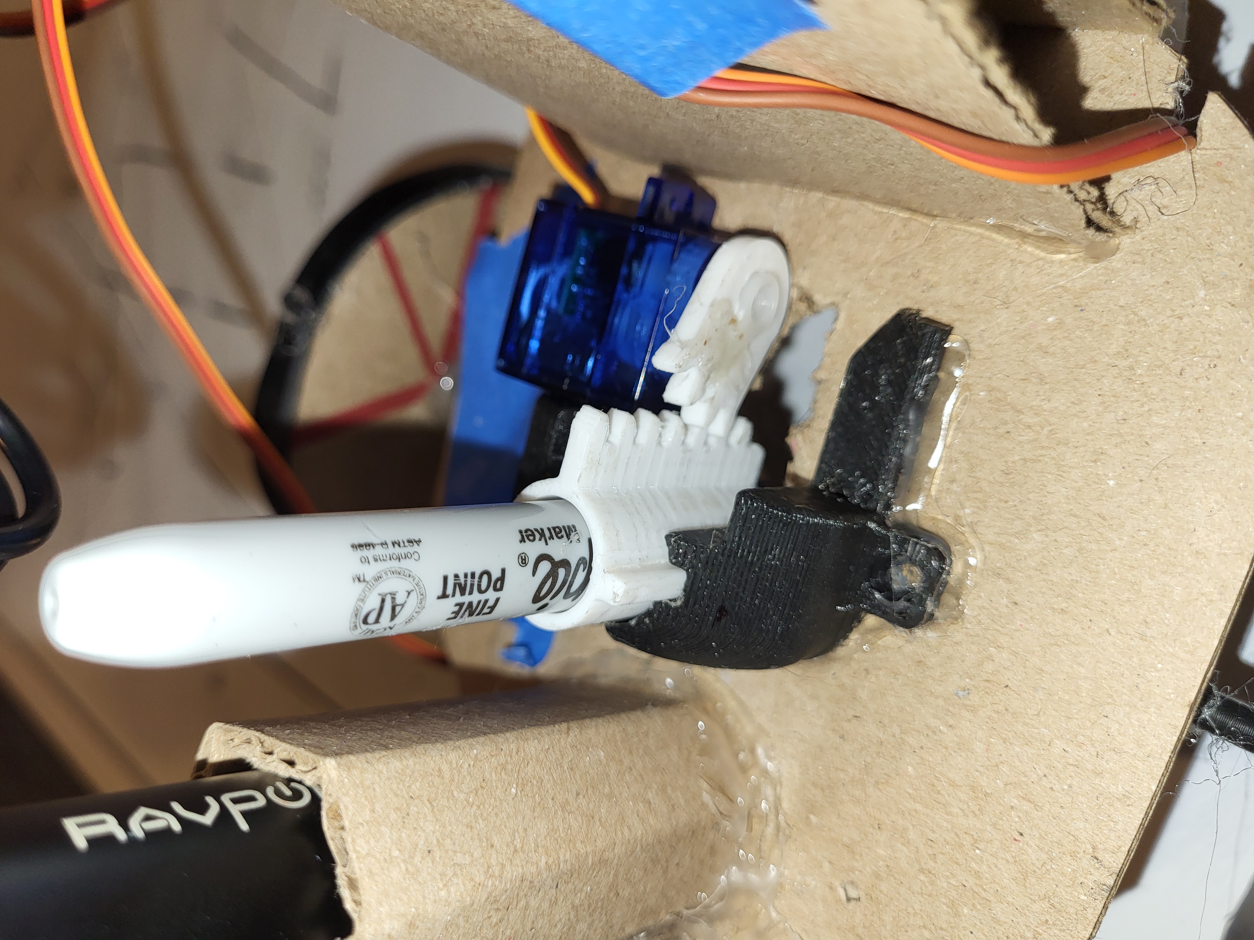
Figure 9: Pen/Servo holder 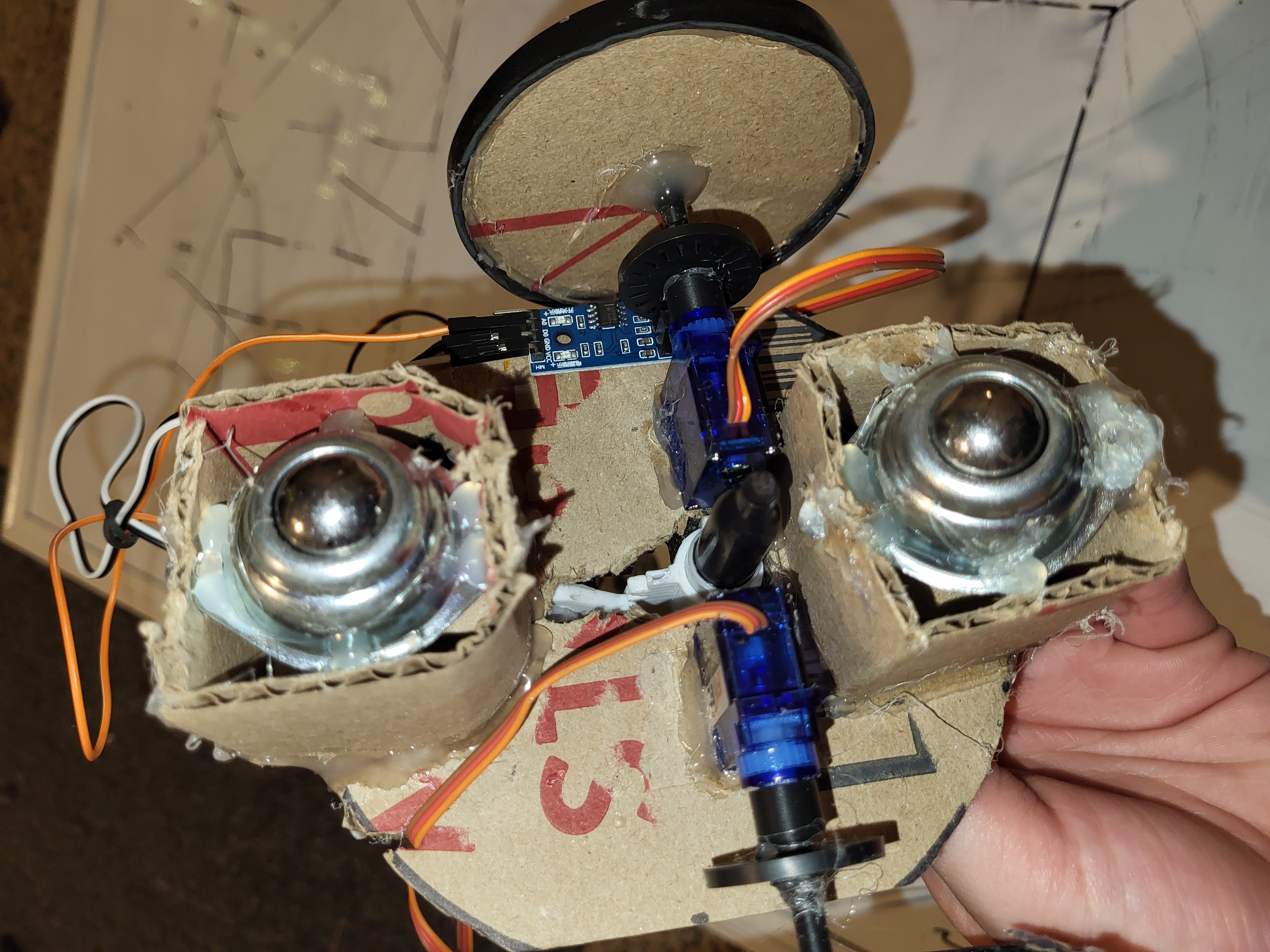
Figure 10: Bottom side of robot. Two continuous servos, the encoder, and the axle connecting the wheel, encoder wheel, and servo.
Results
The main objective of this contract was to design a better user interface for my drawing robot. I wanted a UI that allowed the user to draw lines on a canvas that the robot would then dynamically recreate in real life. And while I believe I have shown decent proof of concept, my final results are not without flaws. The robot has no problem reading the user's input. The issue arises when it comes to calculating the rotations needed to complete a line after already rotating once. As stated previously in the report, calculating an angle after having already rotated previously requires the new angle to be subtracted by an offset angle. Somewhere in the rotate function the final angle needed to rotate the robot is being calculated wrong. When the offset rotation is 0, the final rotation is calculated properly, but once the offset angle is something other than 0, the final rotation is calculated incorrectly. Fixing this would require further debugging, but I have unfortunately run out of time for further polishing and debugging.
To show how the robot performs I gave it three different inputs, and compared the input with the robot's output, judging whether each case is successful based on how similar the input and output matches up.

Figure 11: Successful case
In this case, the robot's output matches the user's input. While it is not perfect, it is close enough that I consider it a success.

Figure 12: Failed case
In this case, the robot's output does not look like the user's input. Rather than making two -90 degree turns (not actually -90 but close) like in the user input, the robot makes one -90 degree turn, then a 180 degree turn (the beginning point of the third line is disconnected from the ending point of the second line, this is because the robot lifts the pen while rotating). This is most likely due to a miscalculation in the rotate function, resulting in a failed case.

Figure 13: Successful case
In this case the user input draws three lines, lifting the pen in the middle line. The output matches the input close enough for me to consider this a successful case.
While the robot fails to rotate properly in some cases, it does succeed in giving the user a more dynamic means of creating drawings with this robot. Given more time to debug the rotate function, I believe the robot would work fully as intended. And while the robot is not working as desired I believe the proof of concept is there.
Here is a video of turtlebot in action:
Conclusion
For this project I expanded upon a drawing robot I had previously worked on for IEEE. My goal for this project was to create a more dynamic user interface that allowed for the user to draw whatever they wanted rather than choosing from preset drawings. I rebuilt the robot from scratch, changing out certain components to improve performance. I also chose to program this second iteration in C rather than micropython. I created a UI that the user can connect to on their phones. This UI gives the user a canvas for which to plot points, creating an image out of a series of lines. The robot would then take the data points generated by the user, process them, and use this information to recreate the drawing. And while the robot fails to properly calculate the required angles for rotations after a few lines, it does show that my concept works and that given more time to debug it can work as intended.
References
[1]
“Raspberry Pi Documentation - The C/C++ SDK,” www.raspberrypi.com. Available: https://www.raspberrypi.com/documentation/microcontrollers/c_sdk.html [Accessed: Apr. 29, 2024]
[2]
LearnEmbeddedSystems, “LearnEmbeddedSystems/pico-w-webserver-template,” GitHub, Feb. 29, 2024. Available: https://github.com/LearnEmbeddedSystems/pico-w-webserver-template/tree/main. [Accessed: Apr. 29, 2024]
[3]
Thomas-Kleist, “Thomas-Kleist/Pico-Servo,” GitHub, Mar. 28, 2024. Available: https://github.com/Thomas-Kleist/Pico-Servo. [Accessed: Apr. 29, 2024]